Testing Your Hardware

Test your QSR Drum Synthesizer hardware using this procedure.

Before you begin

  • Review the general concepts presented in this Manual.
  • Determine your system configuration.
  • Purchase and set up your hardware.
  • Install and test required software.

About this task

This topic describes the recommended procedure for connecting and testing the hardware in your QSR Drum Synthesizer system.

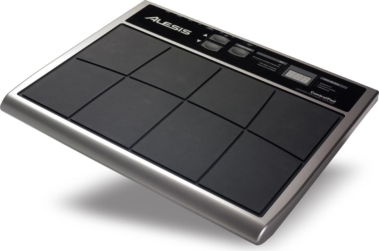
I recommend testing first with a pad controller, like the Alesis Control Pad. The Control Pad requires a single MIDI connection to the QSR. Setup and testing of the Control Pad is relatively simple. After testing the Control Pad with the QSR, you can integrate and test other hardware components.

Refer to the Control Pad reference manual, or the manual for your specific controller, for detailed operation instructions.


Alesis Control Pad

Procedure

  1. Connect the Control Pad MIDI Out port to the MIDI In port on the QSR rear panel.
  2. Power up the Control Pad and QSR.
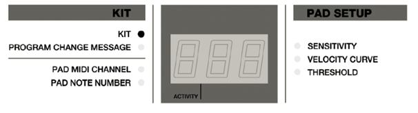
  3. The Control Pad should be in KIT mode (LED next to 
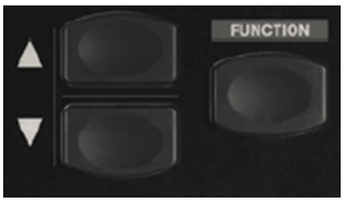
KIT should be lit). If not, press the FUNCTION key until the KIT LED is lit.
    Alesis Control Pad front panel controls
  4. Use the UP and DOWN arrow keys to select a KIT number for testing purposes.
    Alesis Control Pad arrow keys
    Note: You can use any kit number.
  5. Tap a pad and verify that the ACTIVITY LED blinks. This indicates that the pad is working and the Control Pad is sending MIDI data.
  6. Use the FUNCTION key to cycle through modes. Place the Control Pad in PAD MIDI CHANNEL mode.
  7. Choose a pad for testing. Tap the pad to select it for editing. The current PAD MIDI CHANNEL number will be displayed.
  8. Use the UP and DOWN arrow keys to change the PAD MIDI CHANNEL.
    Trouble: The PAD MIDI CHANNEL setting on the Control Pad must match the QSR MIDI channel setting. Otherwise, the QSR will not respond to the messages. Assuming that you configured the QSR Global Settings as recommended, you should select MIDI channel 10.
  9. Press the FUNCTION key to cycle through the modes until the KIT LED is lit.
  10. Place the QSR in Program mode (press the PROG button on the front panel).
    QSR front panel controls
  11. Examine the LCD display and verify that MIDI channel 10 is shown on the last line. If another channel is shown you can change the QSR MIDI channel number to match the Control Pad MIDI channel setting.
  12. Press the FUNCTION key on the Control Pad until the PAD NOTE NUMBER LED is lit. Tap the pad again. The current note number will be displayed.
  13. Use the UP and DOWN arrow keys to set the PAD NOTE NUMBER to 38 (corresponding to note D1).
    Note: Note D1 is used for the snare drum sound in the General MIDI drum map.
  14. Use the FUNCTION button to cycle through the Control Pad modes until the PROGRAM CHANGE MESSAGES LED is lit.
  15. Verify that the Control Pad is set to output no PROGRAM CHANGE MESSAGE ("--" should be displayed). If a channel number is displayed, use the UP and DOWN arrow keys to change the setting.
  16. Press the FUNCTION button to cycle through the modes until the KIT LED is lit.
  17. Using the QSR BANK SELECT UP and DOWN buttons, select the PRESET1 bank.
  18. Select QSR Program number 120 (using the VALUE wheel).
    The QSR front panel LCD display should show "DM5 DRUMS". This is a built-in drum kit program that comes with the QSR.
  19. Connect headphones to the QSR or connect the audio outputs to your monitor system.
  20. Slowly increase the QSR VOLUME while tapping the test pad. You should hear a snare drum sound if the communication is working properly.

What to do next

After testing the MIDI interface to the Control Pad, or other pad controller, make additional hardware connections and test each component. Add one component at a time, to simplify testing. Refer to the documentation for the hardware you purchased, and follow the procedure described in the Testing and balancing Mixes topic for additional information.